
Our Story
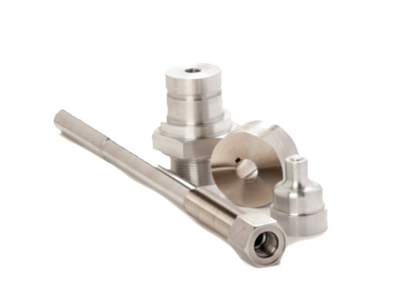
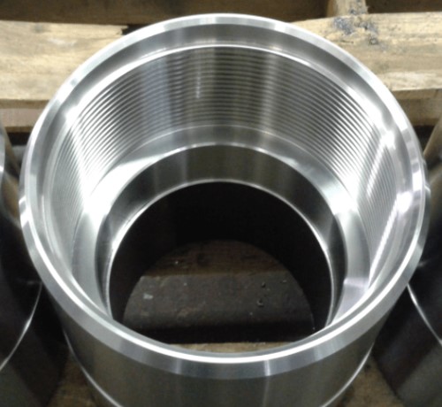
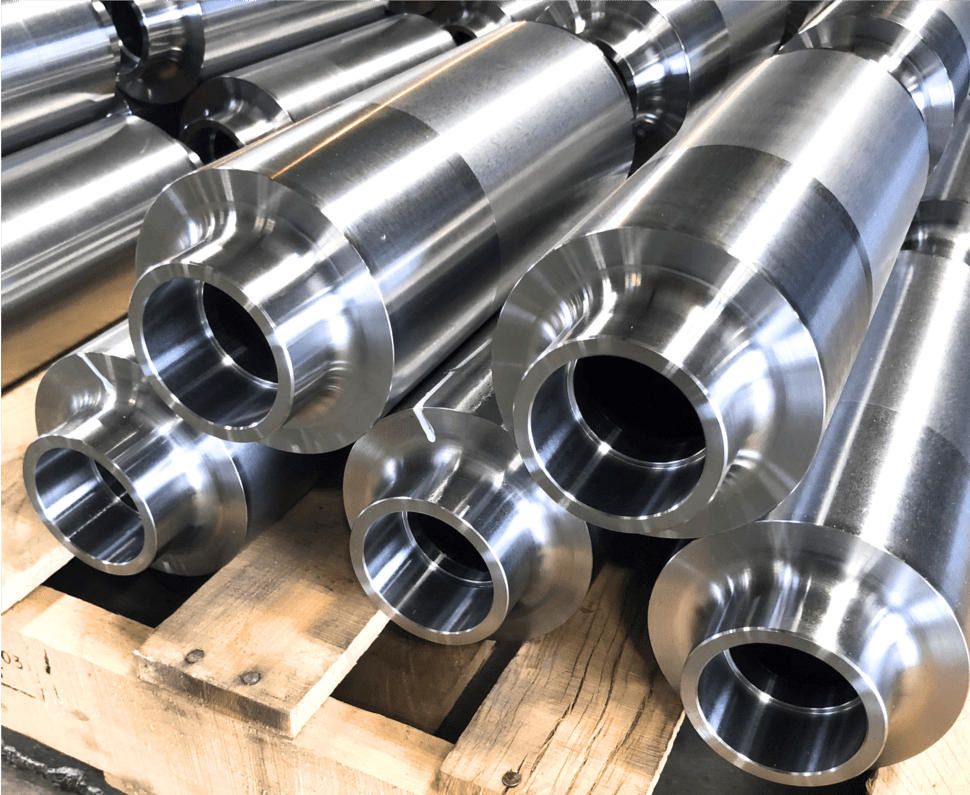
Back in 1977, Precision Urethane & Machine, Inc. purchased a machining facility to service the needs of our growing polyurethane operation. Almost 50 years later, we continue to expand our machining technology to meet the challenges of our diverse customer base. We maintain both CNC and conventional lathes to support a wide array of machining options, from larger 50” diameter single custom machine parts in plastics or metal materials, to small multi-axis products which require 3D CAD development and advanced CAD/CAM programming. We have the experience and technology to meet your needs while keeping cost and quality at the forefront of our process.
Technical Information
Machining Services
- CNC Sawing
- CNC Engraving
- Metal Plating
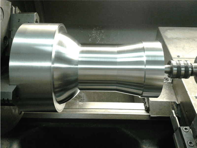
- CNC Turning
- CNC Broaching
- Metal Painting
- CNC Threading
- CNC Deburring
- Comparator Inspections
- CNC Knurling
- CNC Drilling
- CMM Inspections
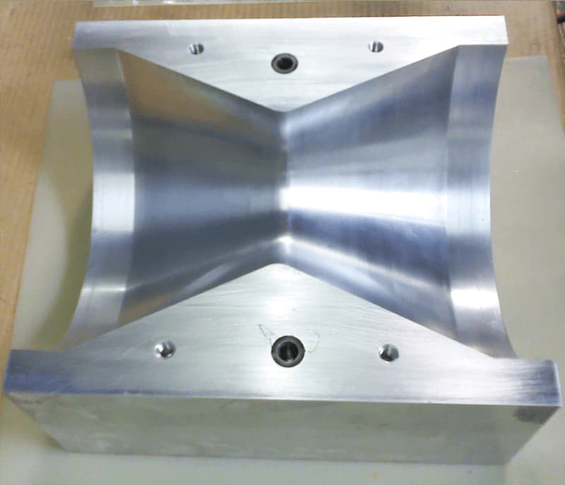
- CNC Milling
- Metal Polishing
- Heat Treating
- CNC Boring
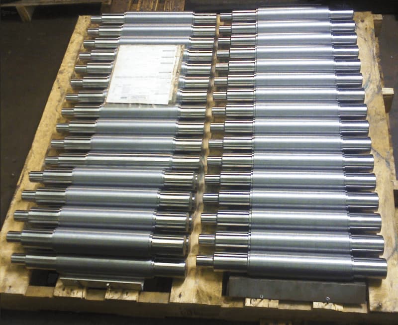
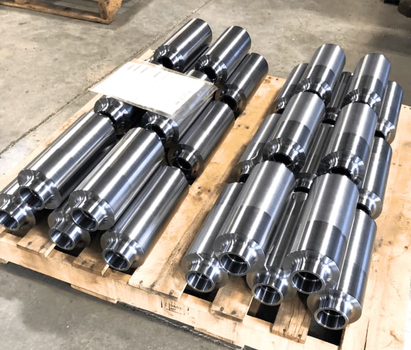
- Volume Production Machining
- Materials Sourcing & Purchasing
Max Weight
2000lbs
Materials
Plastics |
Metals |
||
| Polyurethane | Polytetrafluoroethylene | Aluminum | Bronze |
| Polycarbonate | Polyvinyl Chloride | Steel | Magnesium |
| Acetal (Polyoxymethylene Delrin) | Polymethyl Methacrylate | Copper | Brass |
| Acrylonitrile Butadiene Styrene (ABS) | Polyetherimide | Stainless Steel | |
| Fiberglass | Polyether Ether Ketone | Zinc | |
| Polyethylene | Titanium |
Tolerances
+/-.0002
Programming/Tool Pathing
To effectively operate a CNC machine, tool paths must be created to define the cutting path for the tooling.
The goal of programming a CNC machine is to enable a machine tool to achieve automatic, precise and consistent cutting motion. To do this properly, the CNC requires a set of programming instructions call G codes which are a set of X,Y & Z coordinates which tells the machine how to machine the part. We use the Mastercam CAM system for programming our molds and finished parts. This process is performed by using the 3D model created in SolidWorks, then selecting the surfaces of the model and defining the tooling and the path each tool will take in the machining process. The CAM system will output a video of the toolpath to machine part.
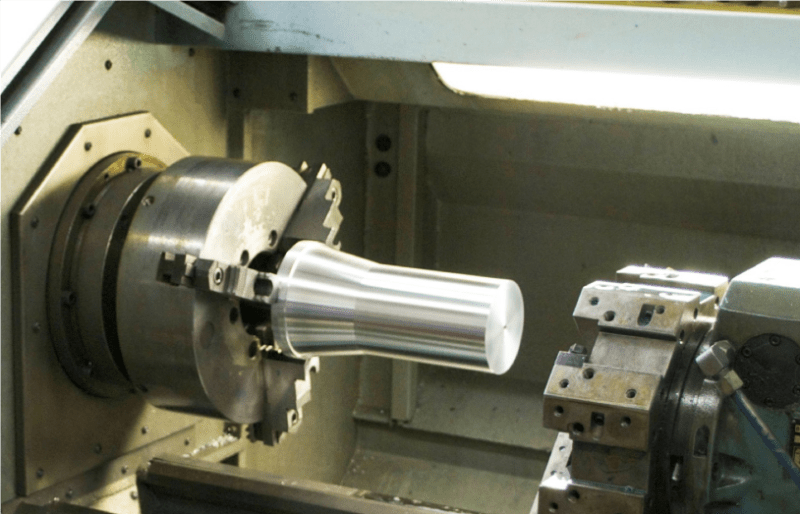
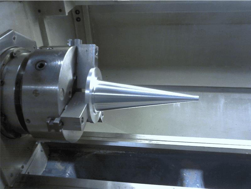
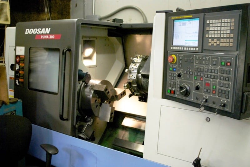
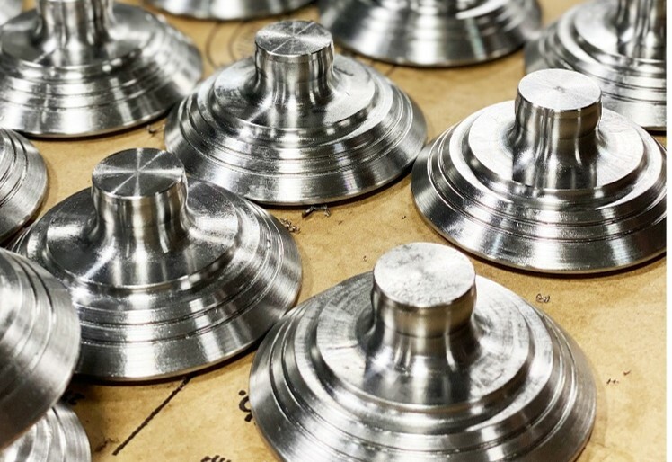
Conventional Turning
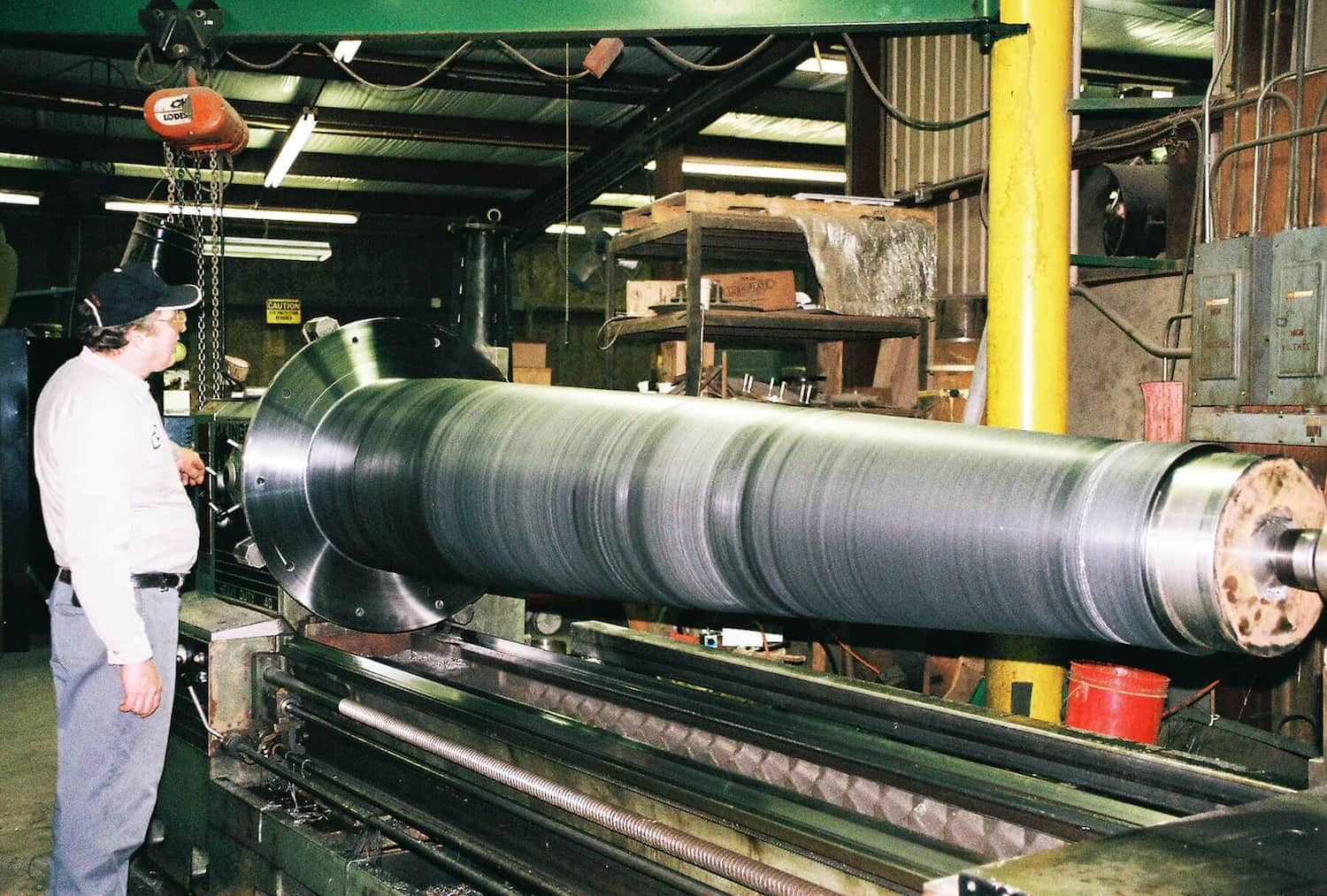
We have 8 different conventional engine lathes which are used in lower volume production applications that do not require contouring or a large number of machining steps involved to produce the part.
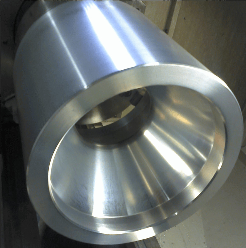
We can machine up to 50” in diameter on our largest conventional lathe.
The primary advantage of this technology is there is no need to generate 3D CAD models or CAM programs to run the machines which in many cases can save time and cost.